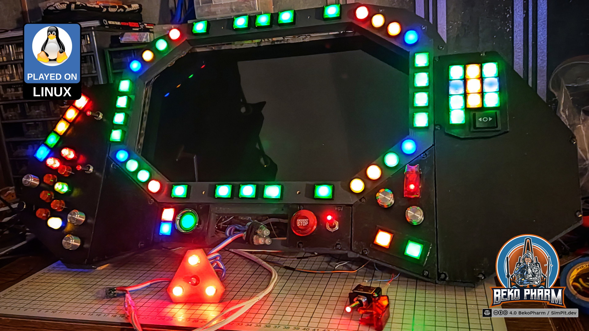
The second version of the Primary Buffer Panel was built directly on the basics developed for version 1. This time it features a wooden frame though and is no longer just cardboard. The idea is to eventually incorporate the panel in a full featured simulated cockpit [in the far future].
It’s design is based on a VF-1 Valkyrie cockpit of the Macross franchise - or Robotech as it is known in some parts of the world (but we don’t talk about this here). More under inspiration.
I was really happy with version 1 and yet, in the end I fell into the same trap as most of the Sci-Fi UI designers in PC games and movies do. All those “little” displays looked great, I had my hexagonal status indicators (nothing says Sci-Fi more like hexagons) but it was not easy to bring any meaningful content on the skewed “screen estate”. And skewed is a CSS literal here.
There was also the thing that I redesigned version 1 inside out so much by now, and moved it around a lot in the house, that it started to fall apart and had to be taped regularly. Yes, the phun of the Primary Buffer Panel falling off happened several times.
I eventually stumbled over a hand drawn design of a VF-1 Valkyrie cockpit of the Macross franchise while looking for inspiration for something with more “screen estate”.
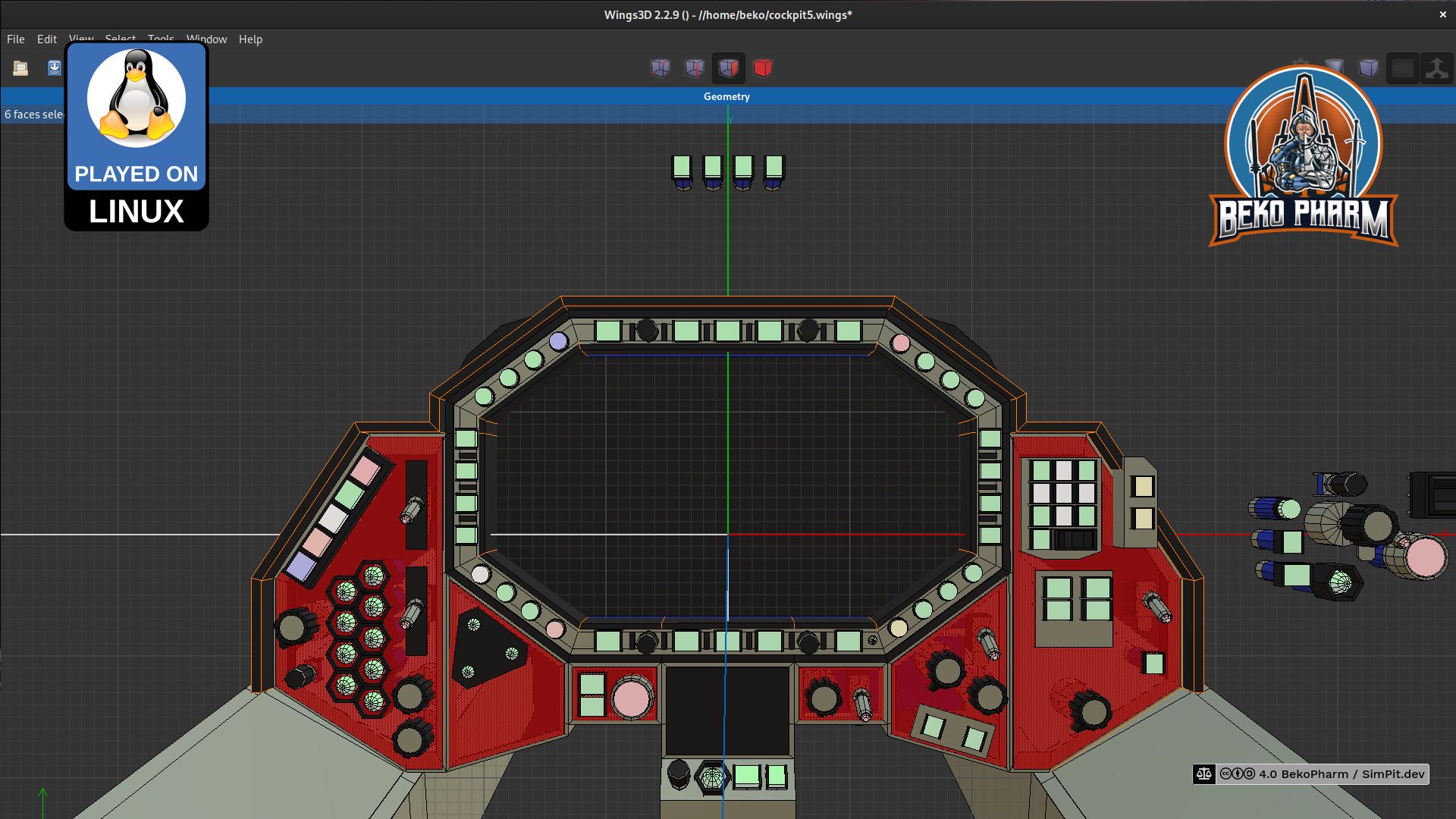
I created a 3D model of the upper cockpit panel in Wings3D where I started to shove around buttons and switches to my liking while keeping close to the original layout. This way I ended up with way more buttons (can never have enough) and get more “screen estate” out of the box while still maintaining a sane layout that would not be in the way of operating something with it later.
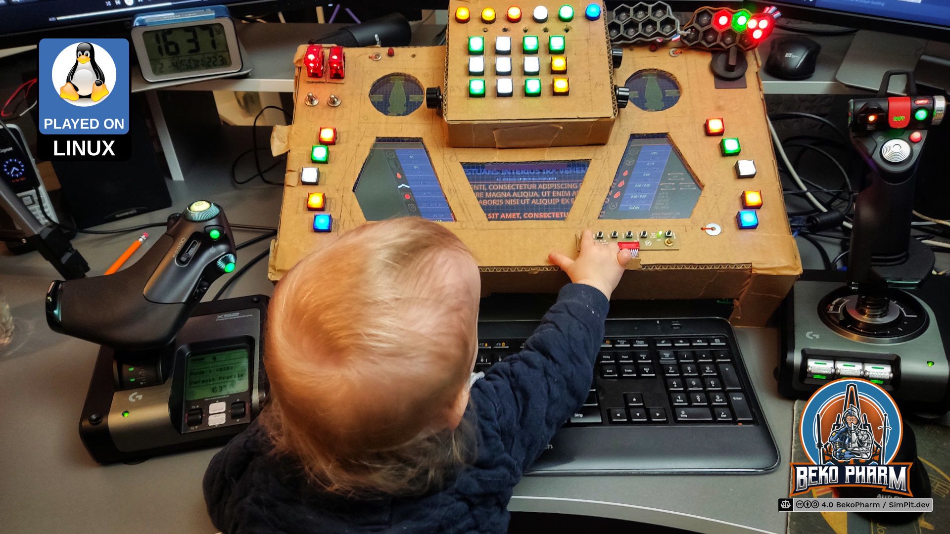
The 3D design was followed by months of doing nothing 😩 until I realized that this would go nowhere without starting. So I found myself sitting down each evening and work on some mock-ups. Even if it was only for one or two hours. At some point would my kids show up and ask questions or hand me tools. Who would have guessed.
It payed off that I went with mock-ups first. Even with a rough 3D model I run into several small issues that had to be corrected.
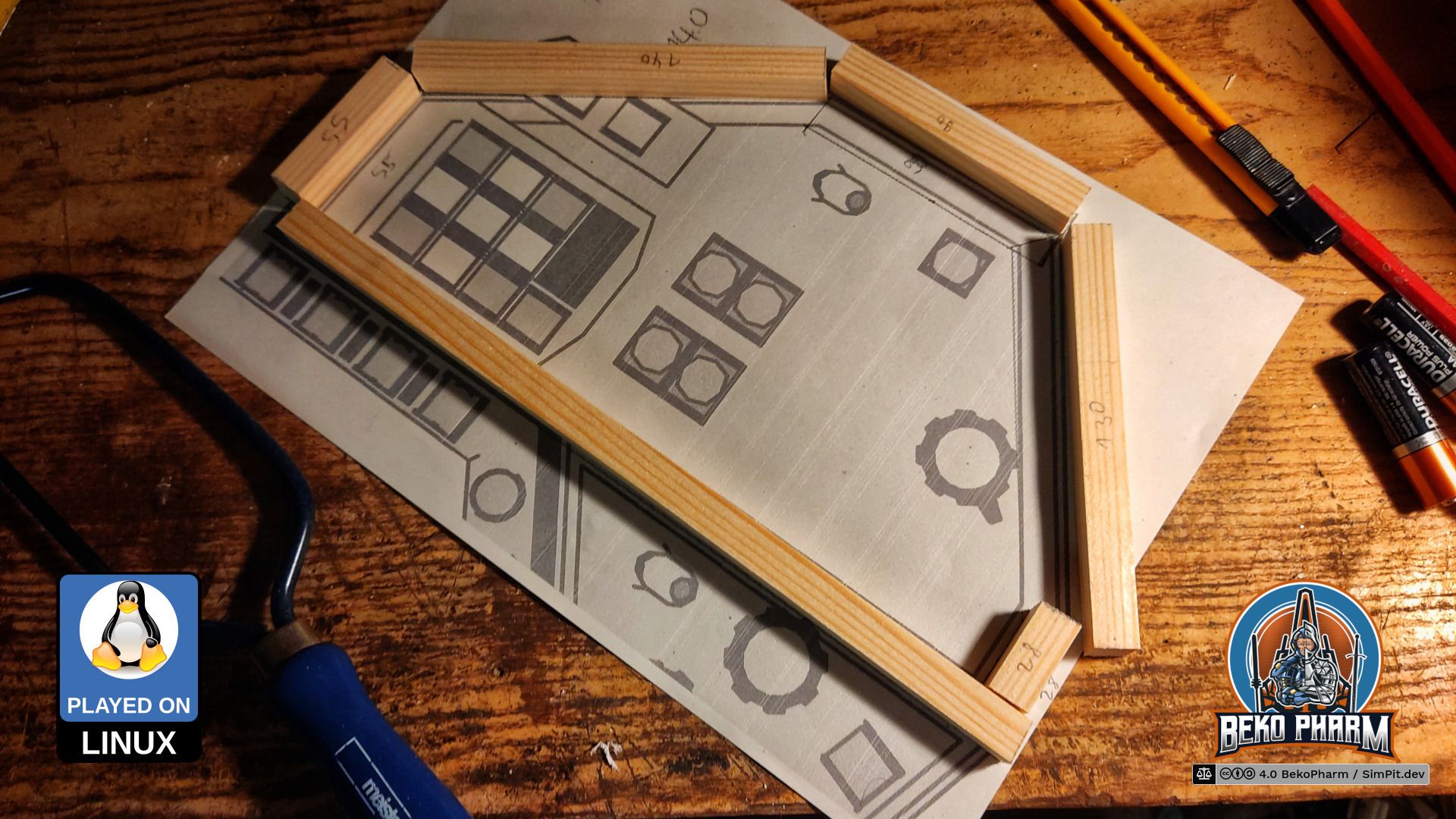
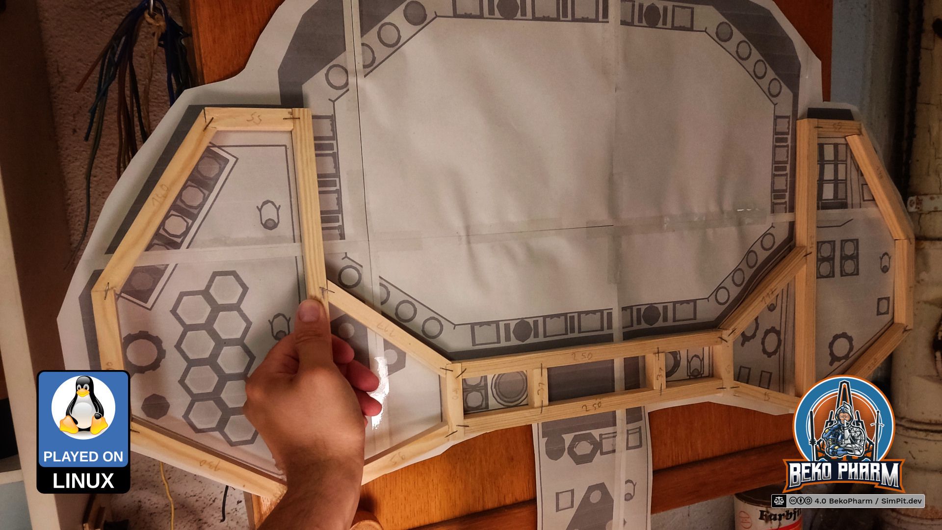
For the Mock-Up I had to export my 3D model somehow first. After messing with various online converters, that all failed to produce a usable result from exported OBJ files I eventually found out that Wings3D has an export to STL built in. Man did I feel stupid. From there I imported the STL into Inkscape and added various A4 papers to the scene to print everything and tape it together. This was the first time that I got an actual idea of the dimensions and wondered what I did get myself into.
It was time to raid our local hardware store where I got a bunch of pine wood for model building purposes. 13x13x1000mm, 19x29x1000mm to be precise - simply because it looked right to me and was available. I built the whole frame with those two sizes. My STL was not exact enough so I had to make stuff up on the go. It was a pretty straight forward process though.
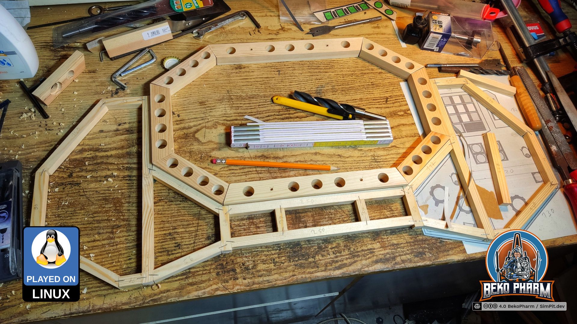
The outer frame is glued but mostly held together by staples. I know what you’re thinking. Heck even my dad told me this would never hold. Hear me out though: First of all I was going to have most of the burden on the inner frame, that is also a lot thicker, and distribute the burden mostly over the covering panels that would be screwed on the top later. Yes, this was flimsy but it held up until everything was screwed together - even for the following photo:
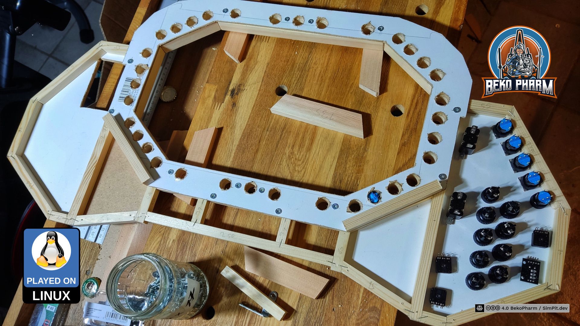
Now things were coming together. The inner panel would hold a shiton of buttons and the LCD later. I can tell you that drilling all the precise holes was no fun whatsoever! I also had to get a new drill for this because I had none with the required size.
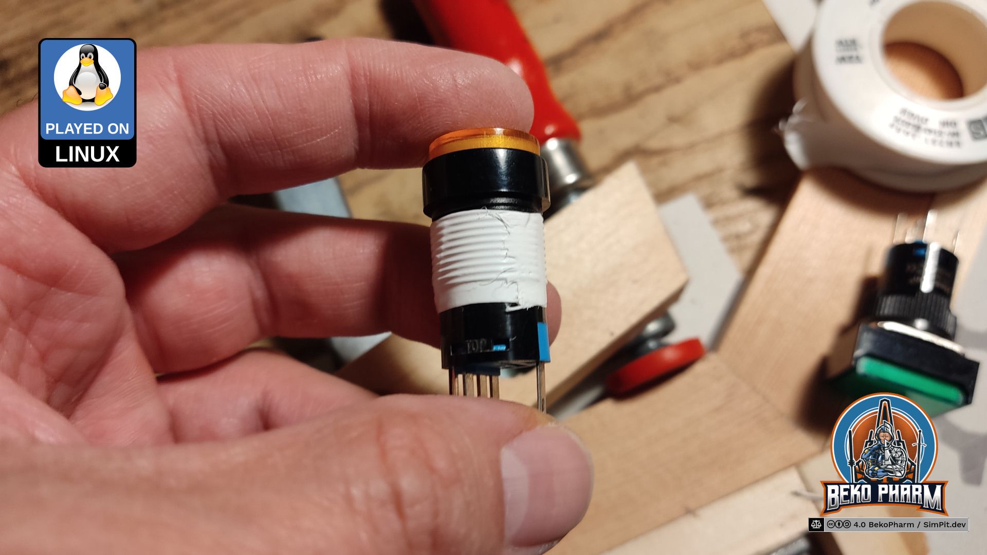
Getting this right was important because most of my buttons would not be able to be fastened with their own screw from the backside. The material is simply to deep for the short length of the screw threads. So every button would have to sit snug in it’s fitting. This worked fine for most holes but some needed encouragement to not wobble around by applying some sealing tape that I usually use for water pipe fittings. It’s not stupid if it works 😛
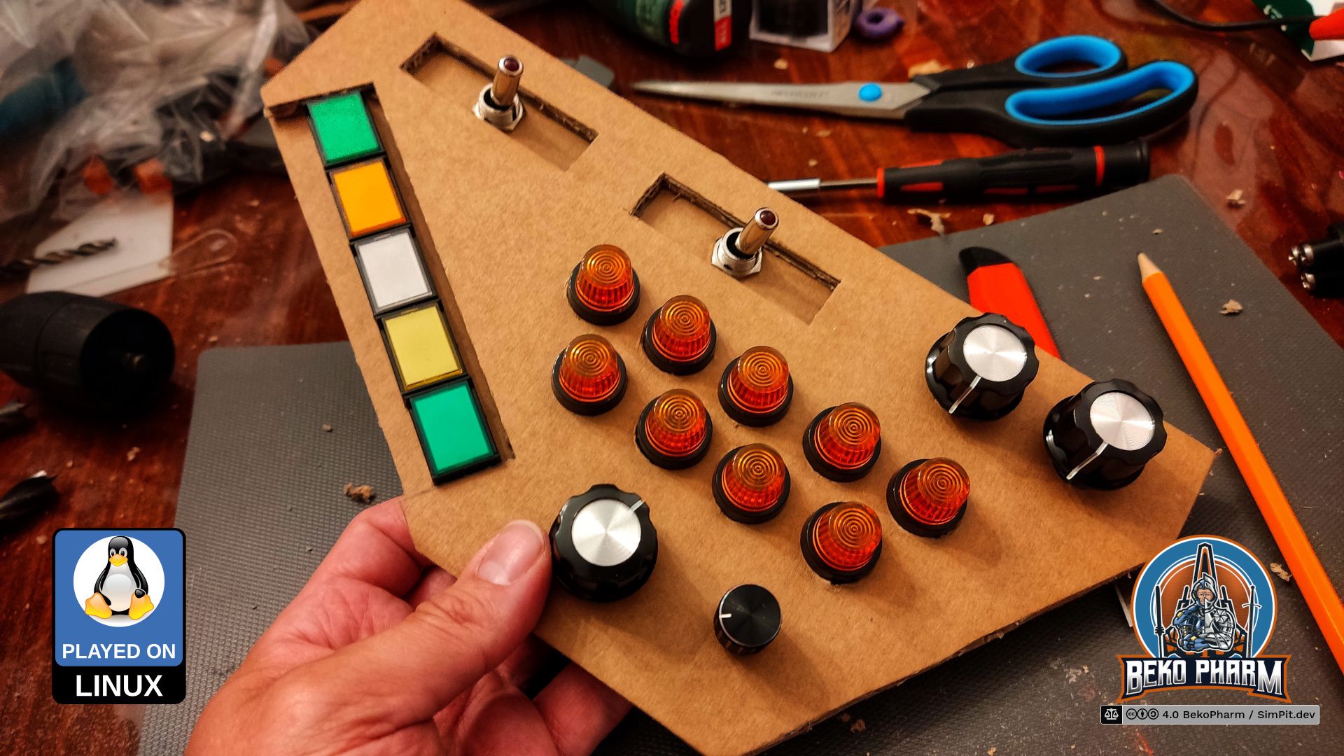
I also can not stress enough how important the cardboard mock-up was. A lot of stuff had to be shifted around slightly for a better fit. The outer frame may be thin but does still introduce an off limits area. In some cases I had to bend the pins of a switch or button to make it possible. Cardboard is very forgiving when it comes to such corrections.
The panels were realized with two layers of thin compressed wood glued together. I only have a shitty jigsaw so I had to rasp the borders into oblivion in the end. A step drill was also a tremendous help because a lot of the parts - again - to not have enough screw thread to be fastened otherwise. This is especially true for the rotary encoders where I found none with a longer shaft so far and have yet to find a way to make these longer. Sadly the advertised products in my mailbox promising to help with enlargement are of no help here 🤡
I’m going to replace the wooden panels with a backlit variant made of acryl glass eventually. The idea is to replace the panels 1:1 with the exact same construction method of two layers sandwiched together.
Next was the backplate that would add a lot of stability to both frames. It connects the inner and the outer frame with screws of various length. The lower support area for the LCD is also already on the picture. I considered adding a little more depth for the wiring of the buttons. Some would be sitting on the LCD corners. I opted to leave it at the depth it is and bend pins again later simply because it would look better this way. I’m also going to add an inner bezel for the LCD frame at a later point.
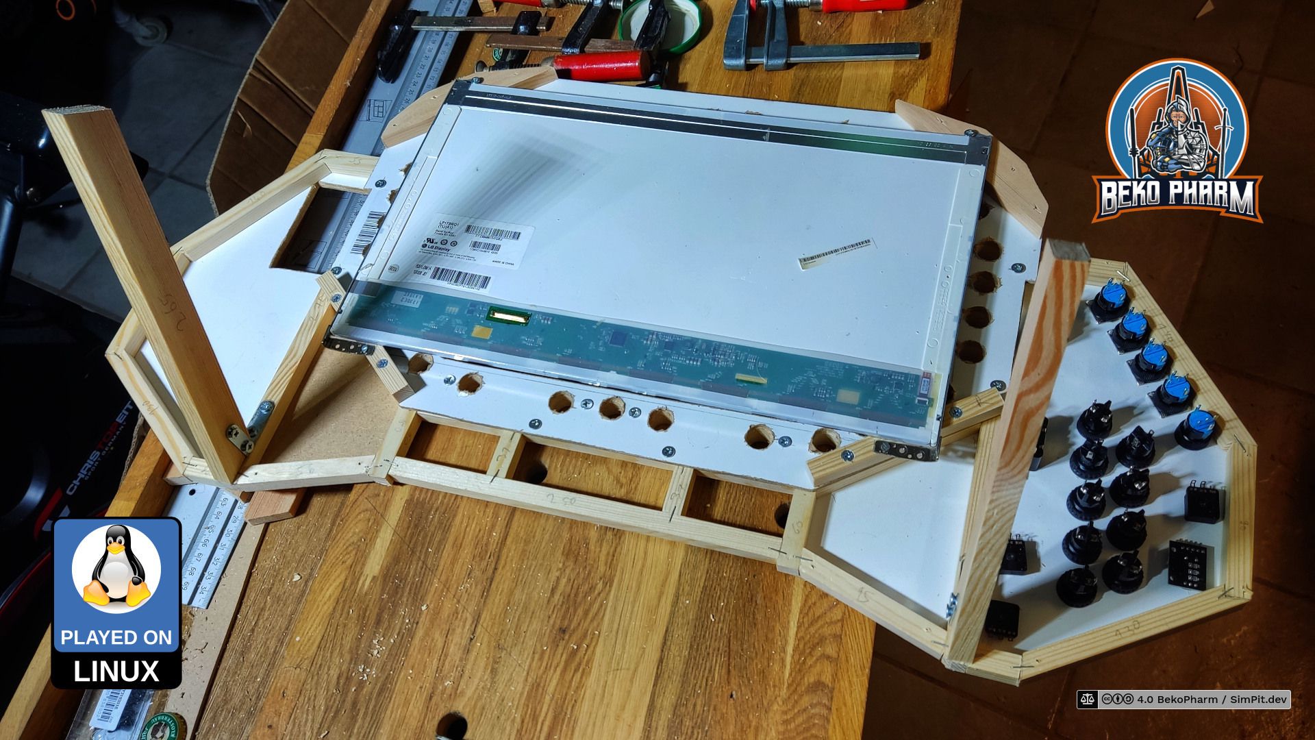
At this point I was in need of a “temporary” stand to work on this more comfortable. This temporary stand was kinda incorporated into the final construction later. I’m going to eventually build a full cockpit around this but for now it’s just sitting on my table. It got additional stabilizer bars later so it wouldn’t wobble on each button press any more. The 17.3" LCD is really a tight fit here and I’m glad that everything worked out so good. I was totally winging it at this point because my STL did not go into too much detail on the backside.
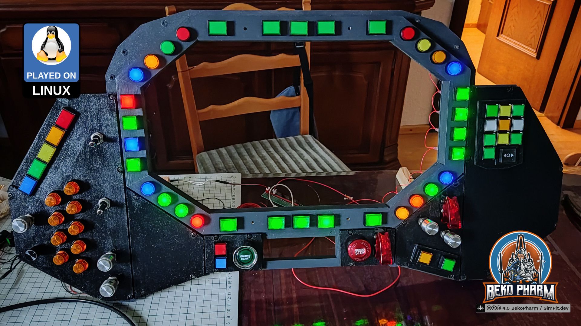
Everything visible was painted in the end. There is not much to say about this. Colours are anthracite-gray and black. The colors don’t really shine, like the picture may imply. The coat of paint was simply not dry yet.
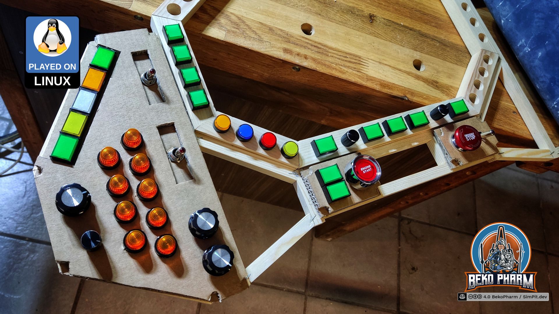
I waited another day for the paint to dry and assembled all parts for the long and dull wiring process. Yes, there are still some empty spaces. For some I’m still waiting for additional buttons to be delivered and for some I’m simply uncertain what to put there. Some gaming sessions should reveal what’s missing. I also didn’t build the lower panel yet because this part would be in the way when put on a table. I’ll probably design a temporary button box on the side for the elements that I was going to put there.
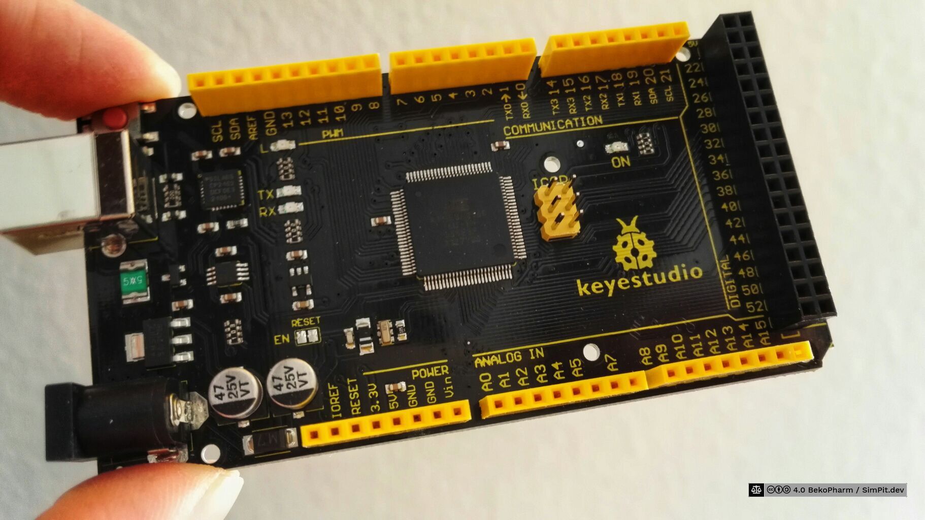
This Arduino Mega proved itself in version 1 already. I got it thinking I’d never run out of free pins on that. I was wrong. It’s also not a HID but a Serial device. I know that it’s some bootloader can be replaced with the HoodLoader2 but I really don’t mind [any more]. There are probably cheaper clones as well but… would you just look at this beauty!
The communication is managed by a Rust daemon. I got the idea and the initial source code for this from github.com/gwilymk/arduino-joystick by Gwilym Kuiper who describes the idea in great detail in his article about Virtual Joystick on Linux. I wrote about this in more detail on my blog as well.
Windows user may either use the mentioned HoodLoader2 or adapt and work with e.g. vJoySerialFeeder but that’s really out of the scope of this article.
My extended source allowing for more buttons and rotary encoders is available at github.com/bekopharm/arduino-joystick. The snapshot there may be not up-to-date though. I’m tweaking this a lot and didn’t push any change for a while.
This page describes actions that may result in a fire hazard or an electric shock. Repeat at your own risk.
Every cockpit needs blinken lights. My status indicators were realized with a Neopixel. That’s a string of RGB LED wich indidivually addressable LED. This way only a single PIN is needed to configure all lights. It has to be a pin that can do pulse-width modulation (PWM) though so choices are limited.
There are various protocols for this. Mine consists of WS2811 modules where plenty of examples exist on the internet.
A dedicated connection is used for power and in theory all LED can be driven from that but in reality we have to keep ampere in mind so things don’t go up in flames. The string is also dead should one module break for good. Not really suited for a real *craft but hey, this is a toy and each string comes with plenty of leftoversreplacement parts 🙃
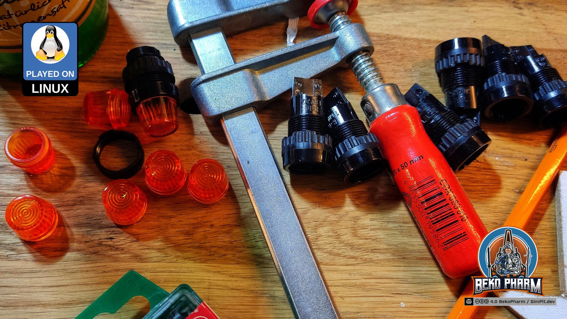
I went for this specific Neopixel because it came with the “classic” LED design. The diffusor is 12mm in diameter and the LED did fit almost perfect in their former hexagonal housings. For version 2 I got some fancy fittings that look absolutely stunning but were designed for old lamps with filaments. So fix this I had to saw the endings off.
After that I had an almost perfect fit for the LEDs. Almost, because the fitting is exactly 12mm in diameter on the inside as well but each LED has 3 tiny hooks to hold a LED in place when stuffed through a 12mm hole. A cutting knife made short work of that though.
I also prepared a small triangular panel for the landing gear. It has no housing yet and is supposed to go into the lower part of the frame but that part doesn’t exist yet. Here is a demo video how this looks.
The LEDs are controlled by Node-RED that does all the plumbing in the end. A custom Rust daemon talks via Serial to the Arduino Mega and listens via Websocket for changes from Node-RED and translates the buttons pushed to a virtual joystick device. The Arduino Mega reads changes for the status indicators and adjusts the LEDs as needed.
Links
Node-RED, Low-code programming for event-driven applications
This page describes actions that may result in a fire hazard or an electric shock. Repeat at your own risk.
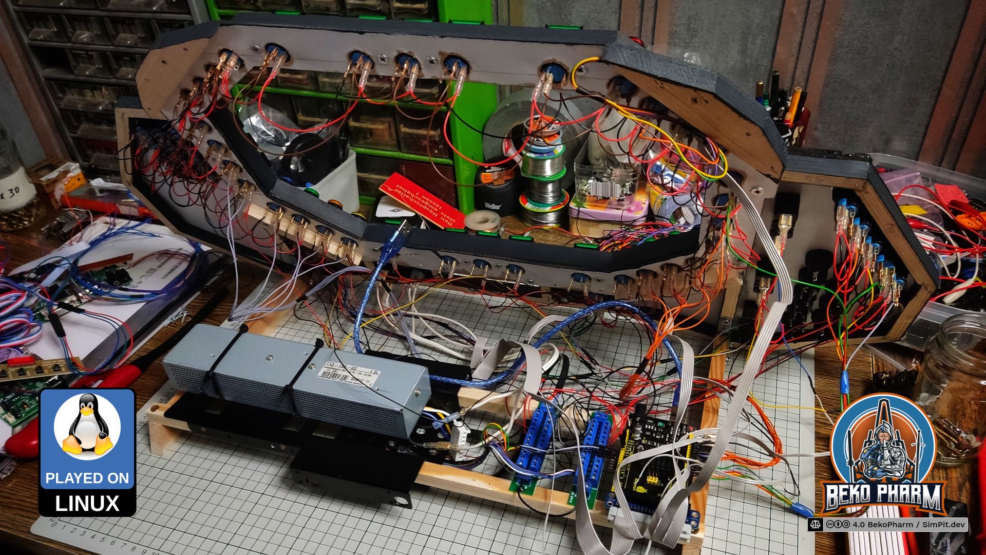
The last step in the construction was wiring everything up. That’s roughly ~250 connectors crimped and I usually remove the isolation with my thumbnail, which is a bad habit 🤪 I purchased crimping pliers just for this and I can totally recommend using such pliers. Used some leftovers from the frame construction to create two rails where everything else was screwed on. The black parts are 3.5" to 2.5" harddisk adapters I had laying around.
The following video demonstrates the dimming with most of the buttons connected already. It works by putting a potentiometer between the two power distribution rails. Stuff that can not be dimmed is connected to the first, stuff that can be dimmed is connected to the second.
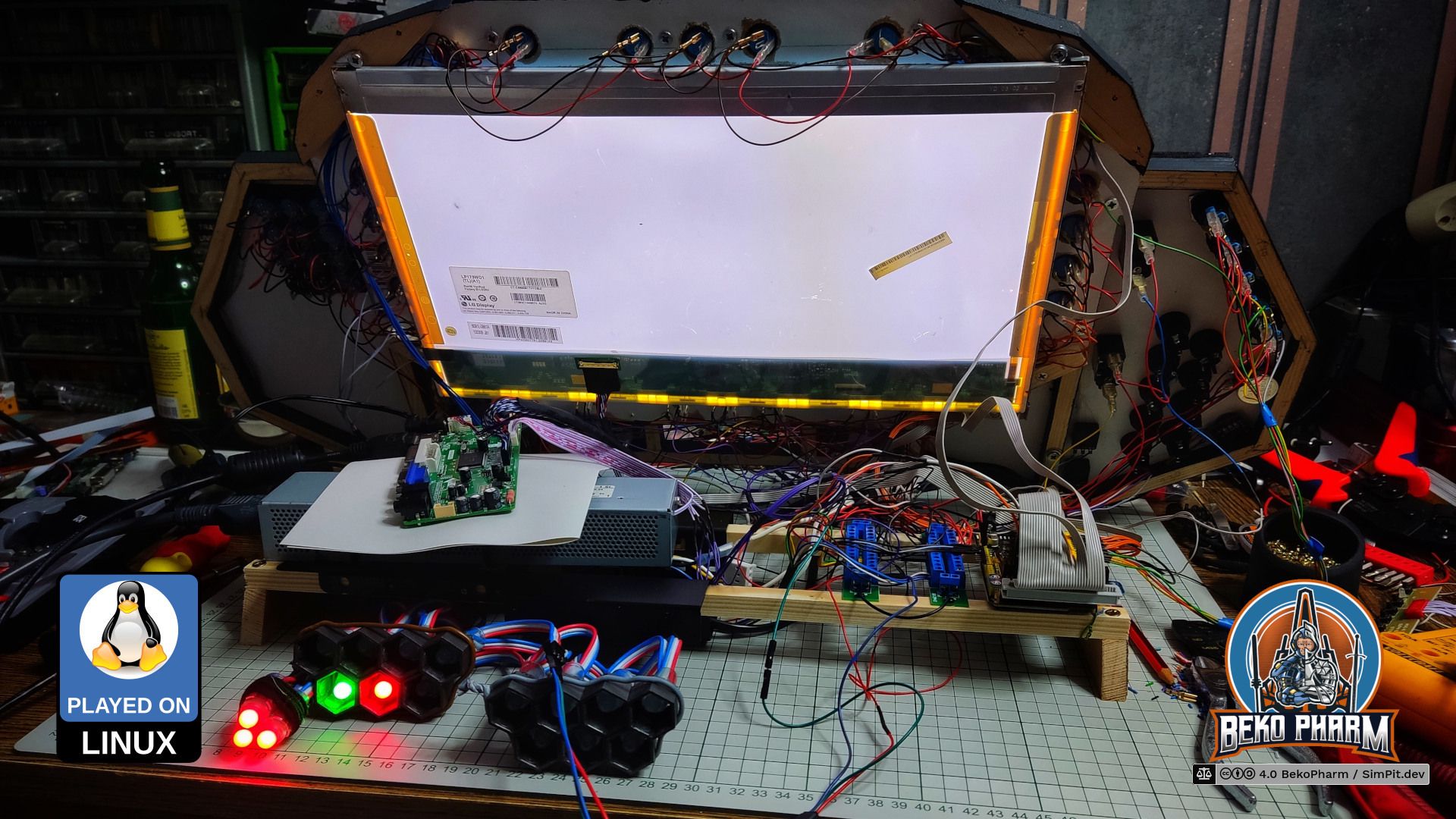
Next was connecting the LCD and see if everything survived the transplantation from version 1. The LCD is very bright on the backside, as you can see. The current version is still missing it’s planned glare shield that will also protect my other displays from the glare of the backside. That’s still to be done though.
After that came some rewriting of the custom joystick source code for the Arduino Mega. Many new buttons wanted to be read. I also removed the original buttons for the LCD controller and connected my own instead. Somewhere during connecting everything I noticed that I made an calculation error and a few buttons could not be connected because I was running out of free pins. So I’ll have to rewire some of the buttons into a button matrix (or use an IO expander - not yet sure what’s best for this).
The blinken lights were next. After that it was time to fix the wobbling. My “temporary” stand was no longer temporary and it was time to add some stabilizing bars. Convincingly this added exactly the space I was missing to fix the LCD controller board to the SimPit. Didn’t really plan this but with this I had all my connectors on the right side (my PC is also on my right).
Not too shabby considering I was winging it at this point.
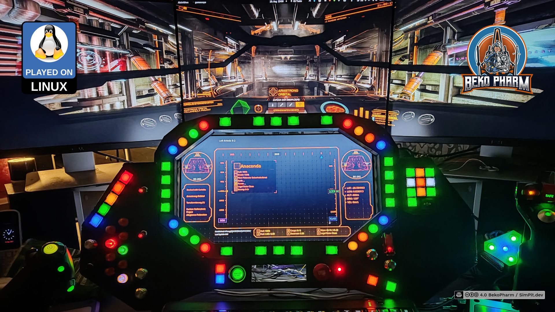
The MFD (Multi-function display) is salvaged from an old laptop. It is not running GameGlass, like so many others SimPits out there do. Mostly because I’m not a fan of touchscreens or vendor lock-in. There is also the little detail that GameGlass is simply not available for my operating system and does not know about all the Space Pew Pew I usually do.
When I was evaluating what to use to program mine I was caught between the difficult choice to learn yet another fancy framework, like Raylib, that would do OpenGL ES 2.0 without X11 on the Raspberry Pi, or OpenFrameworks, or simply go with something I knew already.
In the end I just threw the might of my CoffeeLake at it and went with React since most of the data was already available via Node-RED over Websockets anyway. Also… Arwes is just so cool (alpha version or not) 🤩 and I had some experience with it thanks to my Streaming Overlay that I also wrote with Arwes. Connecting it to Node-RED was just a matter of installing Socket.IO to transport the messages. I rewrote the whole thing for version 2 though because the code for version 1 was a very hacky mess and the older Arwes version was deprecated. The core functionality is still the same though.
Sourcecode plz!
This is the part I’m hacking at most at the moment and I will release the source code to this at some point on my GitHub profile.
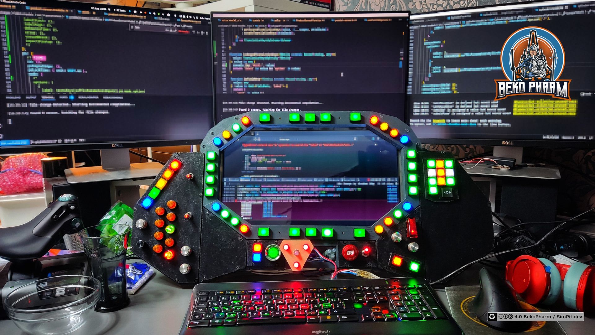
Use aside from gaming
At some point I decided that the additional screen would be very wasted when not used for other stuff as well and since I added some buttons dedicated to multimedia controls already anyway I slowly started to use other parts for my daily workstation use as well. Like… scrolling a website for example.
It also makes a great auxilary screen for programming.